Interfacing Arduino IR Sensor Module
by Lewis Loflin// i took this project from him because i test it and,its working fine..Superb post..
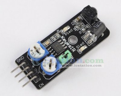
The Keyes Infrared IR Sensor Obstacle Avoidance Sensor board is an inexpensive solution to avoidance detection for robotics and other electronics uses. Costing under $5 with shipping operation is simple and straightforward.
This comes as an assembled module as shown above there are only four pins: +5-volts, GND, output, and EN. Output is an active LOW and has a onboard status LED. It's very easy to interface directly with Arduino, Picaxe, or Microchip PIC micro-controllers.
It also works with the Raspberry Pi with a voltage range of 3-6 volts. Connect Vcc to 3-volts!
The enable pin "EN" will disable the device when HI (Vcc) and enable when LO (GND). The onboard jumper can be left open to allow external control of enable/disable of the module. I see no use for this function and would leave the jumper on and the pin disconnected.
There are two potentiometers on the module one controlling operating frequency (centered at 38 kHz) the other controlling intensity. The detector was designed for 38 kHz and the onboard oscillator circuit is based on a 555 timer. Tweaking gives a little better range but I'd suggest leaving it alone because the useful range is narrow.
It worked well as is. The maximum reliable range in my test was around 30-40 cm and depended on the type of material. A smooth white surface worked far better than a black or rough surface.
The video above shows how this is used with an Arduino Nano.
- Microchip PIC 18F2550
- Assembly language projects using PIC16F628
- PICAXE Microcontroller Projects
- Arduino Microcontroller Projects
- General Electronics Learning and Projects
- My YouTube Videos on Electronics
#define Bit_out 12 // Pin 1-2 Sn74164
#define CLK 11 // Pin 9 Sn74164
#define RS 7  // Pin 4 LCD
#define E 8  // Pin 6 LCD
#define sensorPin 4

#define Line1 0x80  // location LCD row 0 col 0 or line 1 LCD
#define Line2 0x80 + 0x40  // location row 1 col 0 or line 2 LCD

int count = 0;

void setup() {
  pinMode(Bit_out, OUTPUT);
  pinMode(CLK, OUTPUT);
  pinMode(RS, OUTPUT);
  pinMode(E, OUTPUT);

  pinMode(sensorPin, INPUT);

  digitalWrite(CLK, LOW);
  digitalWrite(RS, LOW); // LCD in command mode default
  digitalWrite(E, HIGH);

  initLCD(); // see below
  delay(500);
  typeln("Count = 0    ", Line2);

}

void loop() {
  // below simply prints "Hello World!" on line 1
  //  char String1[] = "Hello world!\n";
  //  typeln(String1, Line1);
  // change a float to ASCII
  // dtostrf(floatVar, X, Y, charBuf);
  // X is min String Width Inc Decimal Point
  // Y is num Vars After Decimal point

  // sensor low when object detected

  typeln("Detector Off   ", Line1);
  if (!digitalRead(sensorPin))   {
    typeln("Detector On  ", Line1);
    typeln("Count =       ", Line2);
    count++;
    typeInt(count, Line2 +9);
    while (!digitalRead(sensorPin)) {} // wait for release
  }

} // end loop

// location is place on LCD display.
void typeInt(int k, int location)   {
  char array1[10];
  itoa(k, array1, 10); // int to string
  typeln(array1, location);
}

void typeChar(byte val)   {
  ssrWrite(val);
  digitalWrite(RS, HIGH);
  pulseOut(E);
  digitalWrite(RS, LOW);
}

void writeCommand(byte val)   {

  ssrWrite(val); // send byte to 74164
  digitalWrite(RS, LOW); // make sure RS in Com mode
  pulseOut(E);
}


// Below we pass a pointer to array1[0].
void typeln(char *s, int location)   {
  delayMicroseconds(1000);
  writeCommand(location); // where to begin
  while (*s)  typeChar(*(s++));
}  // end typeln

// inverts state of pin, delays, then reverts state back
void    pulseOut(byte x)   {
  byte z = digitalRead(x);
  delayMicroseconds(10);
  z = !z; // reverse state
  digitalWrite(x, z);
  z = !z; // return to original state
  digitalWrite(x, z);
} // end pulsout()

/*
To shift LSB out first:
 byte  temp = val & B00000001;
 if (temp == 0x01) digitalWrite(Bit_out, HIGH);
 else digitalWrite(Bit_out, LOW);
 pulsout(CLK);
 val = val >> 1; // shift one place right
 */

void ssrWrite(byte val)  {  // shift data to 74164
  for (int j=1; j<=8; j++)  {   // shift out MSB first
    byte  temp = val & B10000000; // MSB out first
    if (temp == 0x80) digitalWrite(Bit_out, HIGH);
    else digitalWrite(Bit_out, LOW);
    pulseOut(CLK);
    val = val << 1; // shift one place left
  }  // next j
}  // end byteWrite


/*
Hd44780 display commands:
 0x0f = initiate display cursor on blinking
 0x0c = initiate display cursor off
 0x01 = clear display fills display with spaces (0x20).
 0x02 = HOME returns to line one first character
 0x38 = 2 lines X 16 char 8 bits mode. Defaults to 1 line mode.
 0x10 = cursor left
 0x14 = cursor right
 0x18 = Shifts entire display left
 0x1c = Shifts entire display right

 One can also go to a specific location.
 writeCommand(0x80); // begin on 1st line
 writeCommand(0x80 + 0x40); // begin on 2nd line

 writeCommand(0x38); // setup for 2 lines
 writeCommand(0x0F); // blinking cursor

 writeCommand(0x02); // home
 writeCommand(0x01); // clear

 */


void initLCD(void)   {

  writeCommand(0x38); // setup for 2 lines
  writeCommand(0x0F); // blinking cursor
  writeCommand(0x01); // clear
  writeCommand(0x02); // home
}


void ClearDisplay(void)   {
  writeCommand(0x01); // clear
  writeCommand(0x02); // home
}
No comments:
Post a Comment